FBI Vehicle-Tracking Device: The Teardown
by Kim Vetter May 9, 2011

The FBI's use of GPS vehicle tracking devices is becoming a contentious privacy issue in the courts, with the Obama administration seeking Supreme Court approval for its use of the devices without a warrant, and a federal civil rights lawsuit targeting the Justice Department for tracking the movements of an Arab-American student.
In the midst of this legal controversy, Threat Level decided to take a look at the inside of one of the devices � which are generally custom-made for law enforcement. Working with the teardown artists at iFixit, we examined a device an environmental activist discovered on her vehicle in 2005, which she recently provided to us.
What follows is iFixit's analysis of the first-ever dissection of an FBI vehicle tracker.
Above:
Step 1
We finally have one of these on the teardown table! Being in its presence, I can almost feel my civil liberties being flushed down the toilet.
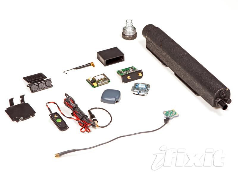
Before we whip out the blowtorches and jackhammers, here's a look at the entire tracking system.
Clockwise from the top, the system is composed of:
- Battery pack
- GPS antenna
-
Transmitter-receiver unit
- Magnetic mounting bracket
The components of the system are all attached to the tracked vehicle with extremely powerful magnets. Some were so stubbornly attached that they ripped out of the mounting brackets to forever remain stuck on the undercarriage of the host vehicle.
Step 2
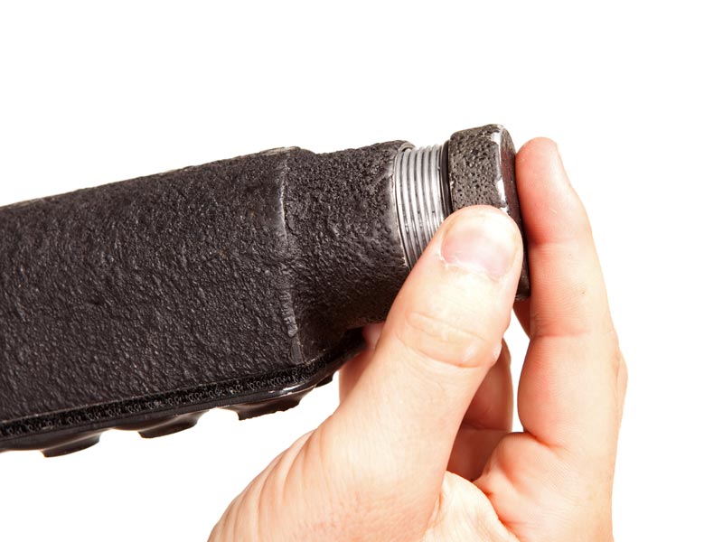
Wondering what kind of technology keeps the tracking device powered? Let's remove the battery pack's end cap and find out.
The device is powered by four lithium-thionyl chloride (Li-SOCl2) D cell batteries.
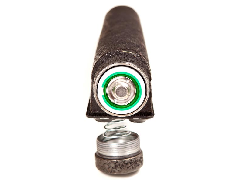
Step 2 (Continued)
Each cell is good for 13,000 mAh [milliampere-hours]! That's about double the capacity of the iPad 2's battery.
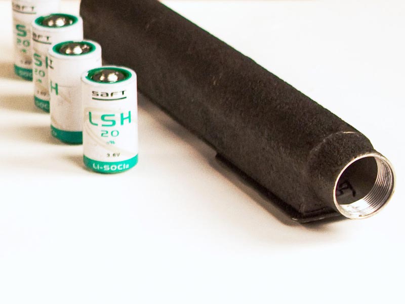
Step 2 (Continued)
These cells are suited for extremely low-draw applications where longevity is needed, making them ideal for powering an always-on transmitter-receiver. Their service life is rated at 10 to 20 years.
Step 3
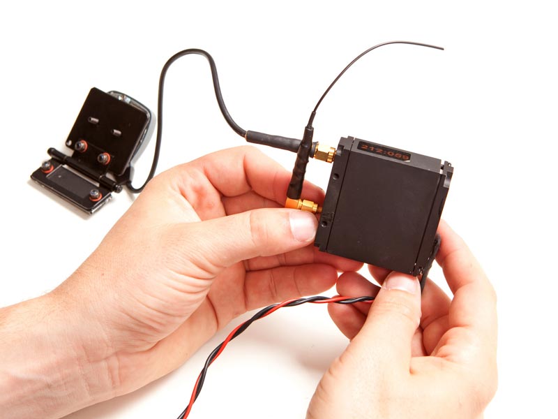
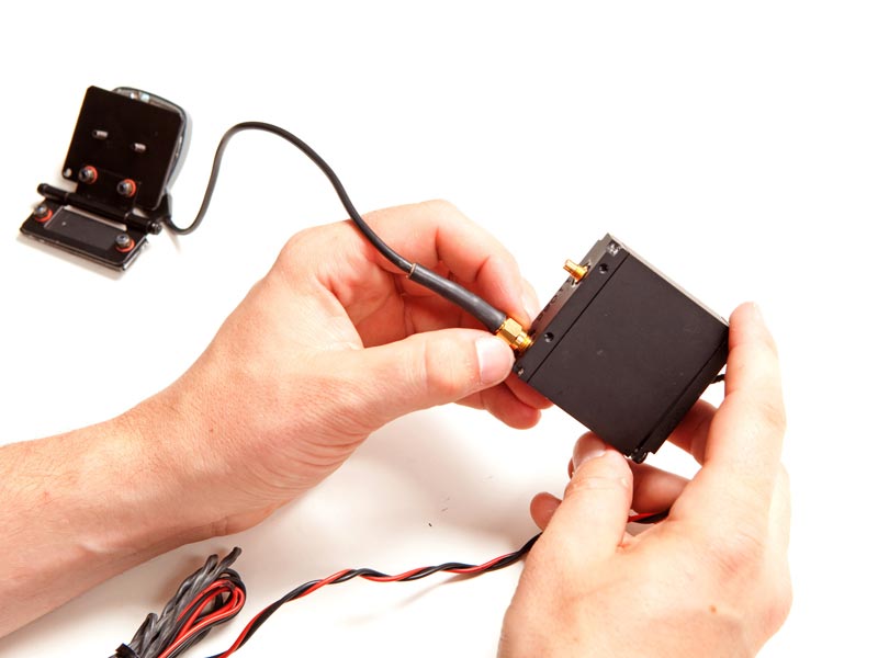
To begin tearing the device apart, we detached the two antennas from their screw-in mounts on the transmitter-receiver module.
Step 3 (Continued)
The short antenna we disconnected in the first picture is responsible for transmitting the location signal to transponders that the FBI would use to find you.
The larger antenna is for receiving GPS signals from satellites orbiting far above the earth's surface.
Step 4
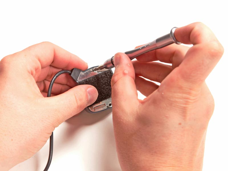
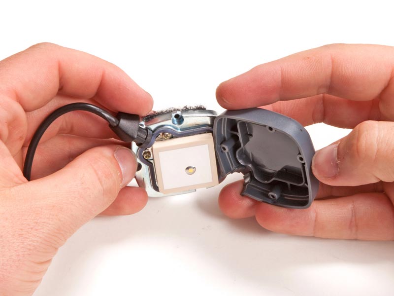
Removing a few Phillips screws allows us access to the innards of the GPS antenna.
Step 4 (Continued)
In keeping with the nonpermanent mounting solutions, the GPS antenna is attached to its bracket with a hefty piece of Velcro.
Step 4 (Continued)
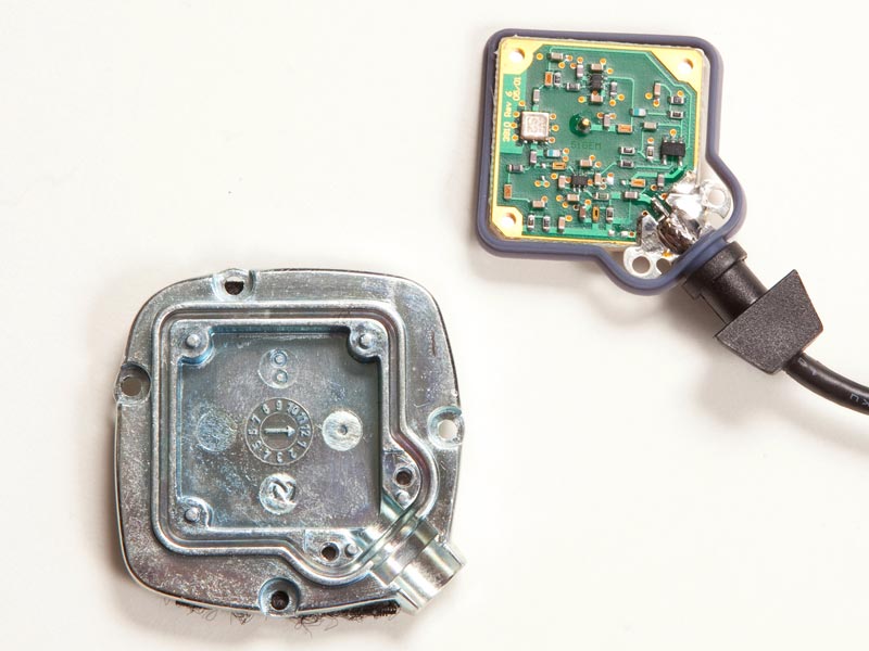
A quick peek at the antenna board indicates it was manufactured by SIgem, a company that partnered with Tyco in the early 2000s to make GPS components.
Step 5
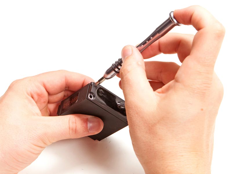
Let's turn our attention back to the transmitter-receiver module.
A few screws are all that remain between us and the innards of this invasive device.
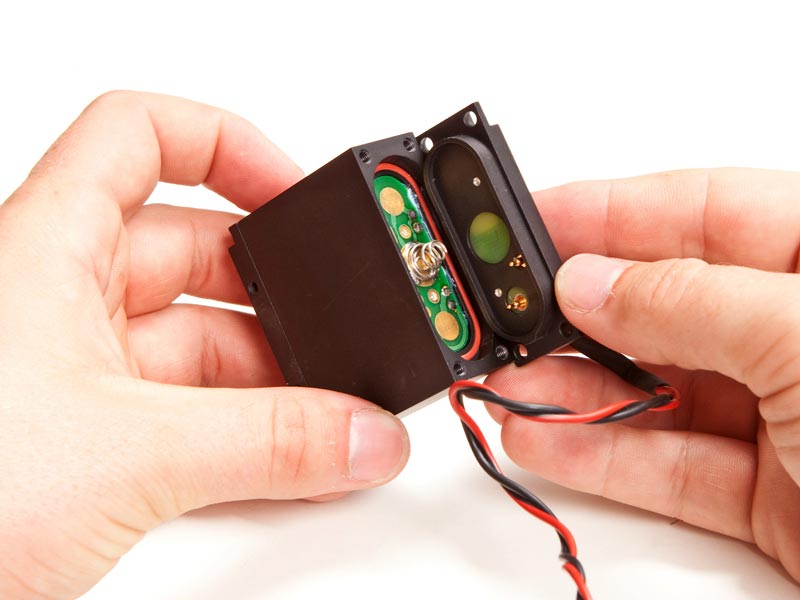
Step 5 (Continued)
It seems that this rear cover is simply a method to connect the module to power. Presumably, power sources (batteries) of different shapes, sizes and capacities can be connected through the same plate to make the tracking device more universally installable.
Step 6
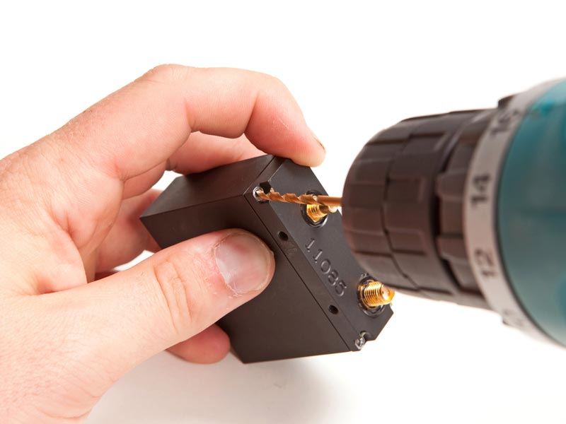
To get to the brains of the module, we focus on the other end cap.
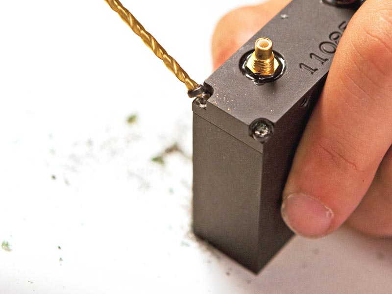
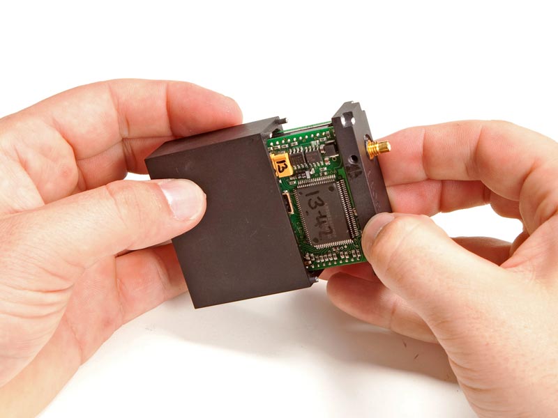
The FBI really did not want anyone tampering with the innards of their tracking devices. The screws were coated with so much thread locker that we had to break out the power drill and eliminate the screw heads.
Step 6 (Continued)

Step 6 (Continued)
Step 7
Upon successfully drilling out all the screw heads, the outer case slides right off the transmitter-receiver assembly.
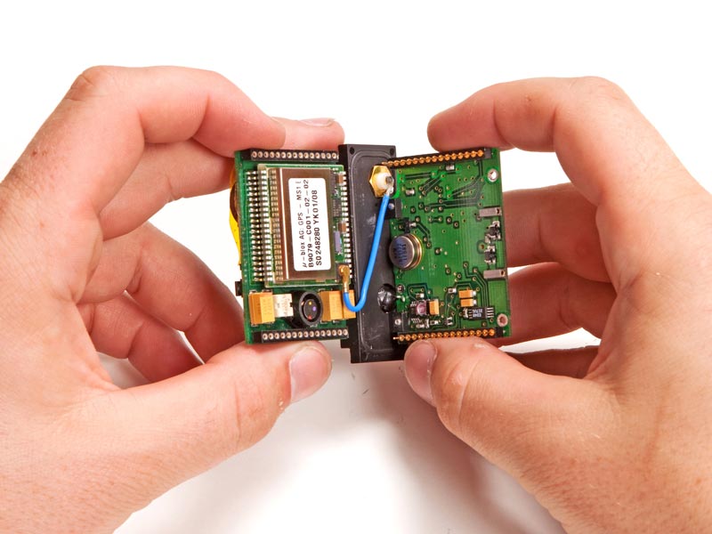
The two modules can be split apart to examine their circuits.
Step 7 (Continued)
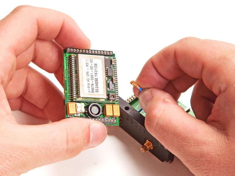
The small blue wire connects the GPS antenna to the GPS receiver board.
Step 7 (Continued)
After disconnecting the GPS board, we can take a closer look at both components.
Step 8
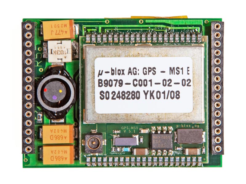
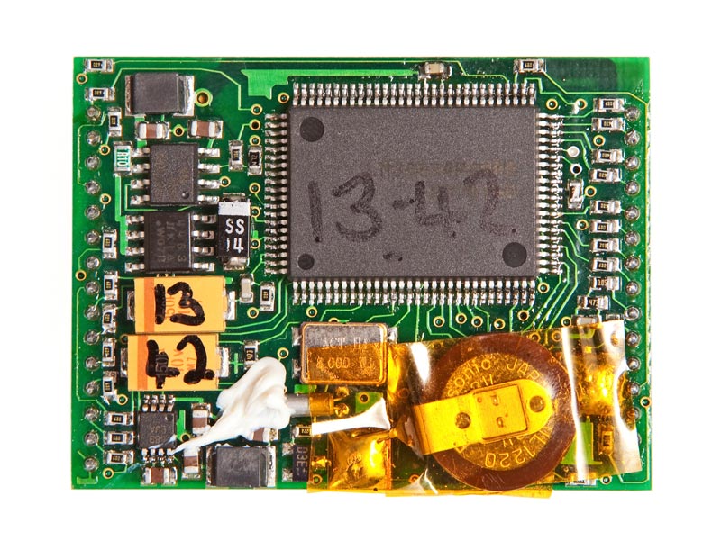
The module providing the GPS signal processing on this device is a �-blox GPS-MS1 that's sort of ancient in the realm of modern electronics.
It was released June 29, 1999!
It features an astonishing 0.125 MB of SRAM and 1 MB of flash memory.
Step 8 (Continued)
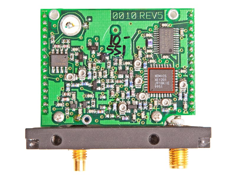
The backup battery on its reverse side powers a real-time clock and maintains the GPS connection if the main power supply is interrupted.
The slightly imperfect alignment of the SMD components on the board indicates that the FBI hand-soldered them to the board and tailored the component choices to their specifications.
Step 9
The larger of the two boards contains the connections for both antennas and is responsible for the RF side of the tracking device. Its notable chips include:
- XEMICS XE1201 Ultralow-power single-chip transceiver
- The XE1201 allows for data transmission and data reception in half-duplex mode.
Step 9 (Continued)
-
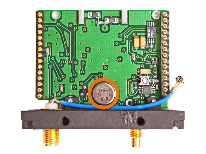
RFM RF1172 SAW (surface-acoustic-wave) filter
-
The RF1172 provides front-end selectivity (the capability to separate signals in one frequency from all other frequencies) in 433.92 MHz receivers.
- Typical applications of this filter include wireless remote-control and security devices operating in Europe under ETSI I-ETS 300 220
Step 10
Tracking device Reparability Score: -10 out of 10.
(10 is easiest to repair.)
- The FBI will find you if you find their tracking device.
- You cannot choose to be not tracked by the FBI.
Y-
ou can legally be tracked by one of these units.
- We'll be right back, the FBI is knocking on our door.
All photos: Jon Snyder/Wired.com
|


